![]()
Recently, I thought I might try to combine modern technology with the styling of 70s hi-fi by converting a pair of KEF Concord IIIs to work with DSP active crossovers, and also upgrade them from 2.5-way to 3-way with all-new drivers. The scheme is based on the same software and DAC that I used for my earlier DIY effort.
Some KEF Concord IIIs (not my particular pair) [nrpavs.co.nz]
I bought the KEFs a few years ago because I thought they looked fabulous. I thought they would sound OK because they’re not tiny and contain two 8 inch drivers. I was wrong: to me they sounded weak and ‘boxy’, so it required no soul-searching for me to decide to modify them irreversibly. Who knows: maybe they had bad capacitors or something, but as you might have guessed, I probably wasn’t going to be keeping them in their original form, anyway.
I didn’t give my conversion project much planning. I already had some Peerless 8″ polypropylene drivers bought very cheap, which WinISD indicated were perfect for the enclosures, and I thought I could cross these over to 3″ drivers rather than the 4″ I used for my big speakers; I duly bought some Monacor SPH75/8 polypropylene mid-bass drivers. I thought about using 19mm tweeters, but in the end plumped for the same Monacor DT25 as I used in my main system because of their small size, particularly the front flange. All pretty cheap.
The KEFs are stylishly covered in a fabric ‘sock’ that was no doubt very cheap to make, but I think looks good. (There is even the possibility of commissioning the very talented mother-in-law to make new ones in funky colours).
I removed the small plinth at the base of the speaker (four long wood screws) and peeled back the ‘sock’ from there to reveal a rounded chipboard enclosure and the three drivers – the Concord is a 2.5-way system. I decided that I would replace one of the 8″ drivers with my mid and tweeter, and that I should therefore invert the enclosure in order to keep all three drivers close together with the tweeter close to the top of the enclosure. I removed the two 8″ drivers but left the original tweeter in position as a ‘plug’ for its hole.
I dusted off the router and made two 18mm MDF flanged discs to replace the 8″ drivers. I should have made the flanges wider because they’re not quite wide enough to take a screw head and clear the necessary foam gasket underneath, meaning I’ll have to clamp them externally. I painted them to seal in the sawdust.
The SPH75/8 is troublingly difficult to mount for a one-off hand-made ‘rapid prototype’: a virtually non-existent flange from the front or behind, and a magnet that is almost as wide as the driver, meaning that if you mount it from the front, there’s almost no gap for the air to flow around unless you widen out the area around the driver from behind. It’s squarish, so if you mount it from behind but don’t want the full thickness of the baffle in the way, you end up having to accommodate the corners, which is fiddly without machining a complex-shaped recess. I ended up mounting the driver from behind, shaping the corners with a chisel. Next time, I will definitely find a woodworking expert to make the ‘plugs’ to my CAD designs!
I needed to make a chamber for the SPH75/8. WinISD told me it should ideally be 3 litres or so – but probably not all that critical for the mid range. I figured the easiest way to do it would be some 110mm plastic piping from the local DIY shop which is quite thick and fairly ‘dead’ if you knock it. I could even buy a ready-made fitting to allow me to plug the end. I duly made an assembly and fastened it to the rear of the MDF ‘plug’ using some bent aluminium brackets. I stuffed it with speaker wadding. The volume works out at about 2 litres, so not far off ideal.

Mid range chamber made from 110 mm plastic pipe and end cap. Hopefully airtight by virtue of neoprene foam gaskets. It is stuffed with wadding .
Using self-adhesive neoprene foam and P-section draught excluder (this really does make a great seal), and plugging various holes, I rendered the mid range and bass enclosures pretty airtight. A top tip: hot melt glue is your friend. It plugs holes and gaps perfectly, and I have found that with a quick application it doesn’t seem to melt PVC cable insulation or ABS, so it’s ideal when you just want to feed cables through a hole in wood or plastic and seal the hole.
Crudely fastening it all together, I fired up one speaker to have a quick listen using slightly modified settings from my big system. I found it really interesting and encouraging, but when the bass drivers were played in isolation there was audible distortion. I worried that it might be the enclosures (they are made from mere 15mm chipboard), but I eventually narrowed it down to the drivers.

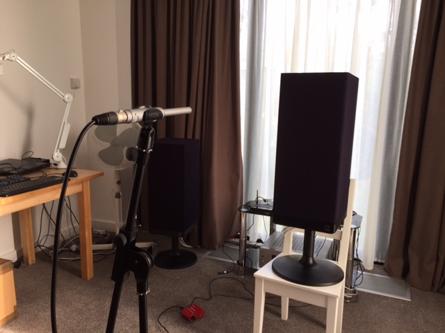
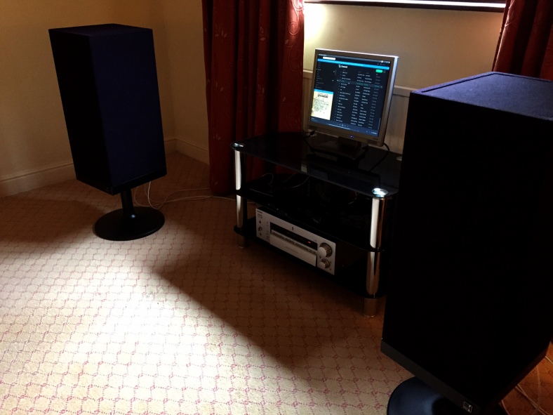
A modified KEF Concord. Those particular pieces of foam are just a temporary experiment, and would be too thick to fit under the fabric cover, anyway.
The mid and tweeter sounded sound spot on.
After building up the second speaker, the next stage was to set them up slightly more scientifically than before. I measured them (woofer near field, and mid and tweeter far field ‘pseudo-anechoically’) and applied roughly the appropriate correction to each driver (phase and frequency response, delay, gain). I also implemented bass extending EQ to aim for the same response as my big system(!) i.e. a 38Hz -3dB point. It sounded pretty reasonable, but I knew the bass drivers were not very good.
Next, I replaced the bass drivers with some cheap but much better Skytronic units (the same brand as my larger speakers). I made the appropriate measurements and compensations in the DSP, and raised the -3dB point to 40 Hz for the sake of reducing the power into the bass drivers.
I added some bracing to the most obviously flappy bits of the KEF Concord enclosures. Broom handle was much cheaper than dowel of the same diameter! The black square between dowel and enclosure is 1mm neoprene sheet. Dowel held in with countersunk wood screws from outside the enclosure.
Yes, the photos make it all look very ‘agricultural’, and the wide angle iPhone lens makes this bit of it look anything but square and perpendicular, but it is actually about right, and the speakers are solid, airtight, etc. where it matters.

Did the bracing change the sound? Can’t say, but it had to be done. I measured the driver in the near field again, and it hadn’t changed at all.
I re-fitted the fabric ‘socks’ – which I managed to get wrinkle-free much to my surprise.

A KEF Concord III with its fabric covering restored
As mentioned before, I ended up inverting the enclosures which meant that I had to remove the fabric ‘socks’ which were stapled very close to the ‘lip’ that is formed at the top of the enclosure. I was worried that I couldn’t find a staple gun that could get right into the corner of this lip, but in the end I found that an ordinary office stapler could do the job, which was fine. At the bottom of the enclosure, there are drawstrings which are pulled tight and tied off. The fabric stretches, so it forms a very flat covering.
The coverings are in pretty good condition for speakers over 37 years old, with just a couple of snags and small holes. They have faded from black to a very dark blue over the years which is only obvious if any of the non-faded material becomes visible through any slight misalignment. New coverings could be made in a variety of colours, but I think it would be preferable to retain the moderately coarse texture of the original material if possible.
Something that seems to have been an irritation to the previous owner is that the tops of the speakers are capped off with a square of hardboard covered with fabric, and over time these have warped, with the corners rising slightly. These have been re-applied by the previous owner using No-More-Nails or similar, to no avail.
In the end, I restored the fabric caps by carefully removing the material from the original hardboard, and stretching them over sheets of black-sprayed 2mm aluminium, fastening them to it with carpet tape. These now fasten to the tops of the speakers using Velcro. They look really good. I gave the pieces of cloth a rinse in warm water because they were looking a bit grotty, having taken the brunt of spilled drinks at parties over the years I imagine. It looks to me that it would be possible to give the whole fabric sock a proper wash, and it would survive OK.
I resprayed the wooden plinths with black satin paint, and the same for the 1970s speaker stands with casters.
I also decided to try the option of some of the original ‘inverted mushroom’ stands. I bought some of Mk IV ‘donor’ speakers, but unfortunately had to do a bit of metalwork to make these work with the Mk III. They now look ‘the business’, and I am very much enjoying their sound.
October 2017: Step Response Measurement
I decided to measure the speakers for time alignment. In order to do this, I measured with a microphone at tweeter height and 1m away from the speaker – just to make it the standard measurement position. I used REW to make the measurement using a sweep from 10Hz to 20 kHz and duration about 24s.
This is the result I got:
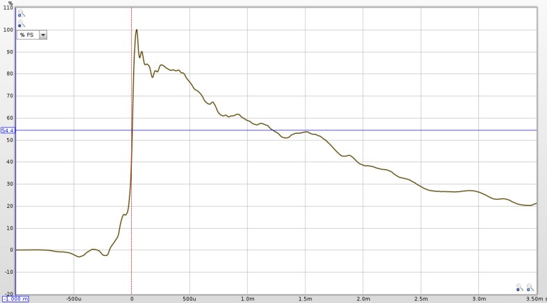
I am assuming that this shows that it is pretty reasonable. In Stereophile’s 1997 article on measuring speakers they show a similar image:
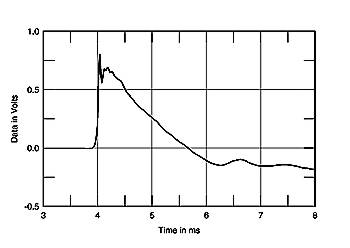
Fig.11 shows a good step response produced by a time-coherent, three-way loudspeaker, with the outputs of the three drive-units adding in-phase at the microphone position. There are not that many speakers that produce this good a step response. Of the speakers I have measured for Stereophile, only about 10—models from Quad, Thiel, Dunlavy, Spica, and Vandersteen—have step responses this good.
Fig.12 shows a more typical step response, again of a three-way loudspeaker. This time there are actually three step responses apparent in the graph: a narrow, positive-going step response from the tweeter; the next, negative-going step is the midrange unit (as will be seen, it’s connected with opposite polarity to the tweeter); with finally a slow, wide positive pulse from the woofer.
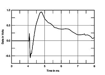
If you do a Google Image Search for ‘stereophile step response’ the results are quite interesting: true step responses are still quite rare.
Scalford Hall 2017
I took my KEF Concords to the HiFiWigwam show in March. The room may have been smaller than last year’s, and I didn’t think the speakers sounded as good as they might. Nevertheless I found a few nice comments on the web.
All rooms were great but the things that got me going back for more –
I was able to do the same ‘party trick’ as my other DIY system, where I showed that changing the crossover frequencies and slopes in real time – even quite drastically – had virtually no audible effect on the sound. If, however, we listened to, say, the mid range driver in isolation, the change was plainly obvious. I would say that this was what you would expect from a correctly set up system with not-too-bad dispersion characteristics, but most people had never encountered it before. The ‘trick’ depends on all the filters being calculated and implemented on-the-fly, and the fixed driver correction and in-room EQ being implemented as separate layers that are overlaid on the crossover filters. I think this demonstration is a kind of sanity check that your setup is somewhere near where it needs to be.
I can’t say why this is considered so unusual, but the fact that it is could go part of the way in explaining why most speakers sound a bit ‘odd’, and why speaker design is considered to be a mysterious art rather than a very straightforward procedure. It seems probable that the results would not be as transparent with a two-way speaker as a three-way because this introduces several new factors into the equation: significant driver beaming – a phenomenon that cannot really be corrected or neutralised – and issues with the drivers having to cover wider frequency ranges. Also, non-linear phase crossovers introduce “phase rotations” through the crossover.
[Last edited 30/06/17]

Very interesting read. Just more photos next time with the various phases of work, and especially the “workarounds”.
It will make the read all more interesting and instructive!
LikeLike